N Gauge Show
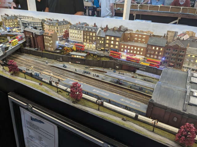
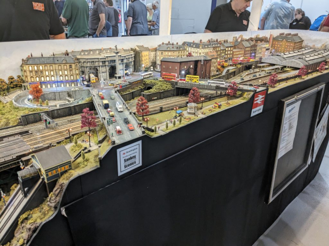
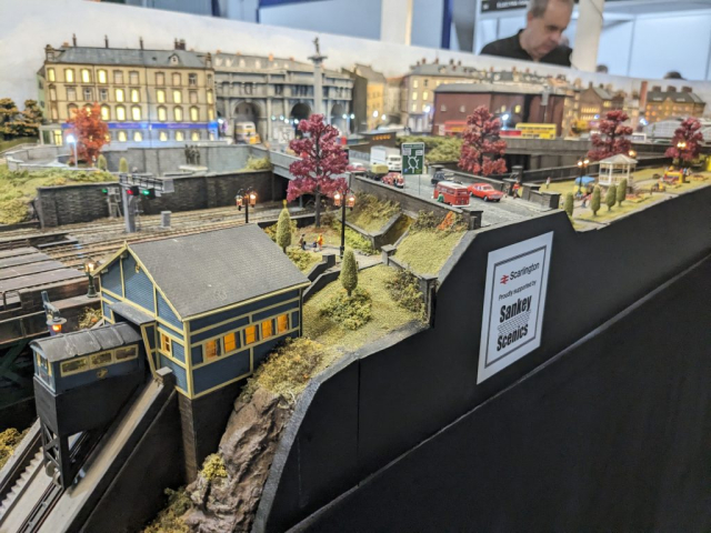
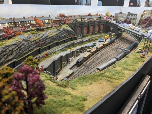
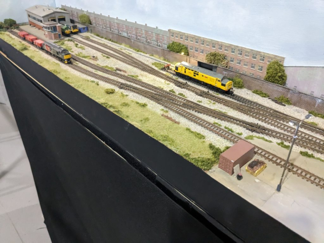
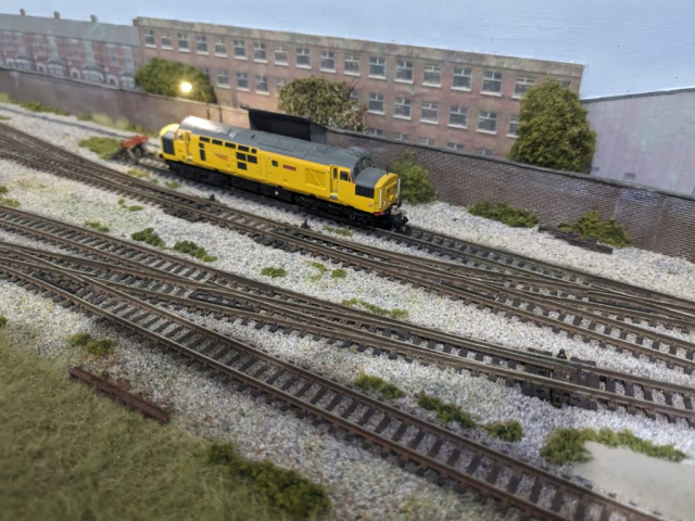
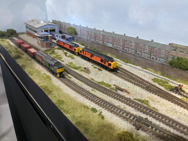
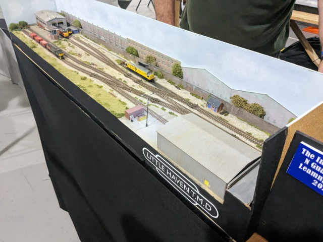
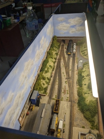
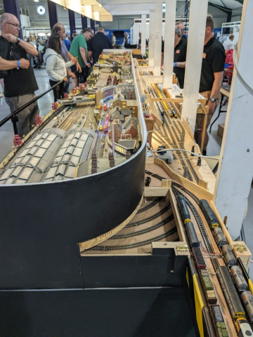
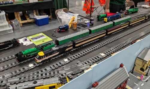
On Sunday 10th, we headed up to Leamington Spa to attend the N Gauge show, affectionately known as TINGS. As a family we’ve adopted a new practice, we take the girls with us – drop them in which ever is the nearest town/city to explore/shop for the day and the boys go to the exhibition. Win win.
That day proved the better option to attend as the day prior recorded the hottest day of the year so far! On the Sunday the venue doors even had to be shut a few times due to rain showers!
As primarily n gauge modellers we always think it’s worth the trip to TINGs – not having to rummage through boxes looking for stock, you just know it’s all n gauge!
What did we pick up? Well, were we actually pretty restrained – we picked up some of Severn Models brass ladder and step kits, a pair of N gauge society snow plows and that was pretty much it!
Layout Progress
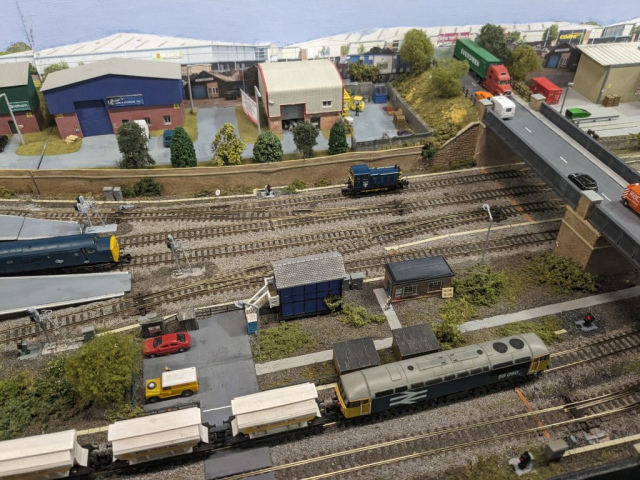
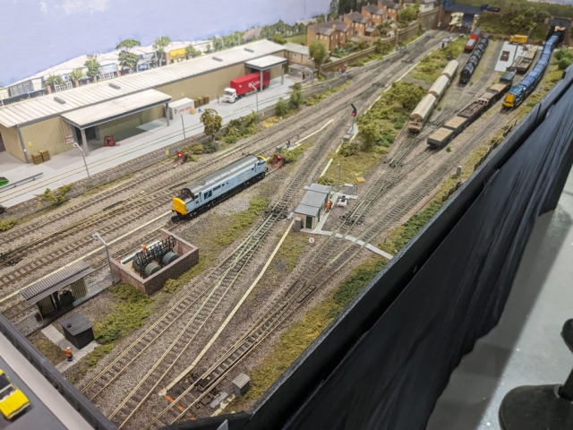
It’s been a busy month for us on the modular layout, and yes, I still owe you an article on the background of the modular layout and what we’ve adopted and why.
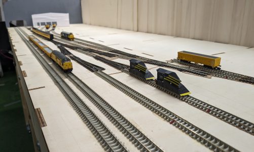
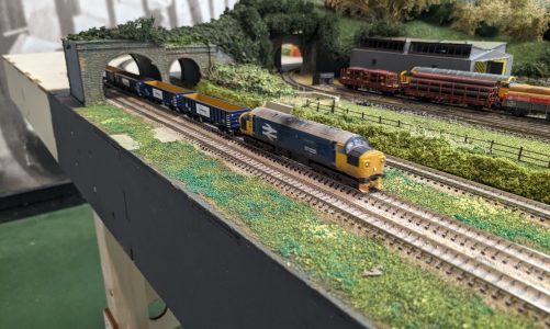
But to progress, we’re working on the left most board of the 3 that will form our home layout.
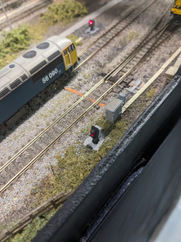
The ‘rules’ of the modular dictate three running lines at the front of the board, separated by prescribed distances etc etc to be consistent. Turns out, this lends itself well to the layout we’re building but we want to have points in the third line. The modular system has electrical connections coming in from the neighbouring board (with may or may not be DCC) and we also want to be able to use the third line in our layout which will be DCC and use block detection. To achieve this, there needs to be isolators to disconnect the line from the incoming feed and connect it to the home DCC bus, but since we’re using block detection it’s a little more complicated.
Here are the scenarios we need to be able to handle:
- Incoming feed to the 2 rails that makes up the ‘incoming feed’, for simplicity assume DC and refer to as +ve and -ve. Requirement: Isolate the line from the incoming feed
- With the line isolated we need to connect the common rail to the DCC Bus Requirement: Connect the common rail to the DCC bus
- The line has 3 blocks in it, when using the incoming feed these all need to be joined together, when using the home DCC these blocks need to be connected individually to the detector channels Requirement: Switch the 3 blocks between the incoming feed (for DC operation) and for home DCC connect the blocks to the 3 individual detector channels.
So we need a bunch of switches to accomplish this – scouring the internet landed me on this latch switch that is a single mechanical latching switch but provides 6 single pole double throw switches within it! Perfect!
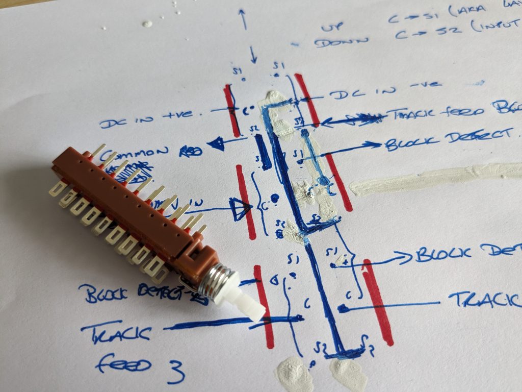
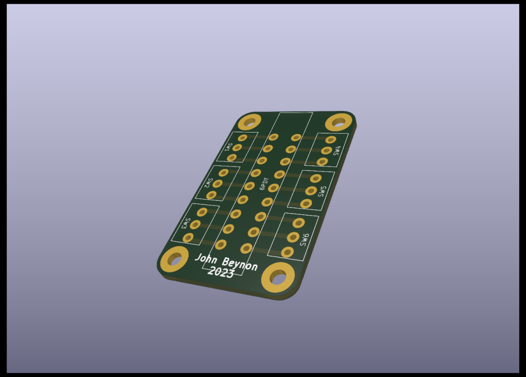
Initial attempts of wiring it up based on the rough schematic I had drawn up proved successful but not happy with the appearance I wanted to improve it. So I opened up KiCad and produced a PCB which I sent over to JLCPCB and had it produced in China for £4.85 delivered to me in just over a week! The latch switch will mount in the centre and the screw terminal blocks will be added to the side – this version will need some ‘jumpers’ across the terminals but a final version will be produced with copper tracks so only the connections to the track and block detectors will be needed.
Ok, so that’s the switching dealt with – having refreshed the grey matter with KiCad I went down another rabbit hole around inter-board connection. We’ve adopted pluggable chocolate blocks for connecting to a neighbouring board – these are cheap, functional and relatively easy to get hold of, the left side of the board needs a trailing male plug and the right side has a female connector on the inside edge. From our first run connecting up boards there was some confusion on the wiring and which rail is which so I set about designing another PCB. Here’s the result:
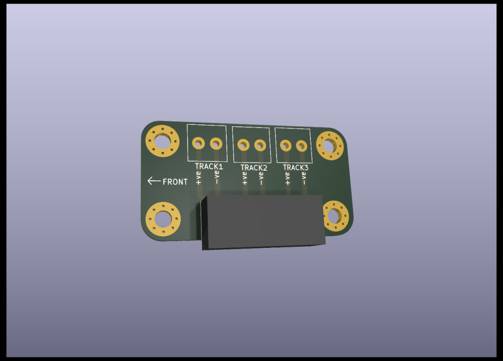
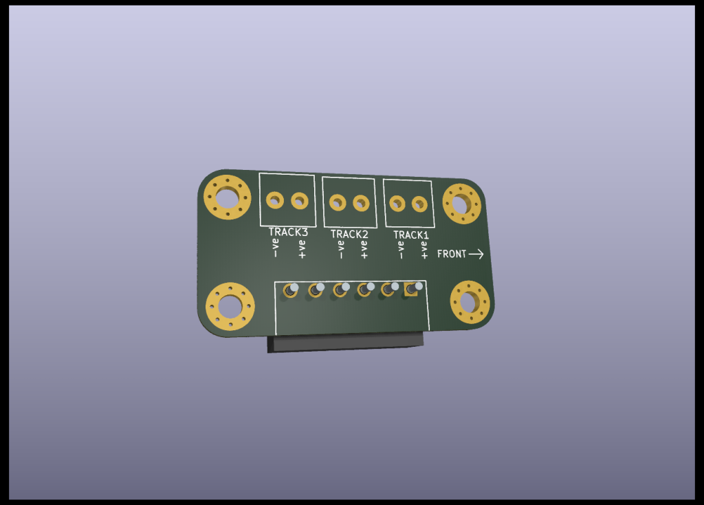
This is the same board, but I’ve used both sides – the front side is for use on the left side of the board, and the back side is used on the right side of the board. The track feeds will be connected to screw terminals at the top and then a plug connector inserted the other – this connector may terminate to a chocolate block, or a connector into one of our own boards or even a connector to a foreign modular system – these boards are due any day now so October’s update will include them.
Turn out modifications
Something we’ve never been happy with is the size of the mechanical bit on PECO points, we’re going to be using DCC Concepts Cobalt Digitals so we always remove the spring and that got us thinking, could we replace the mechanism with a smaller, more discrete mechanism that is centre operated
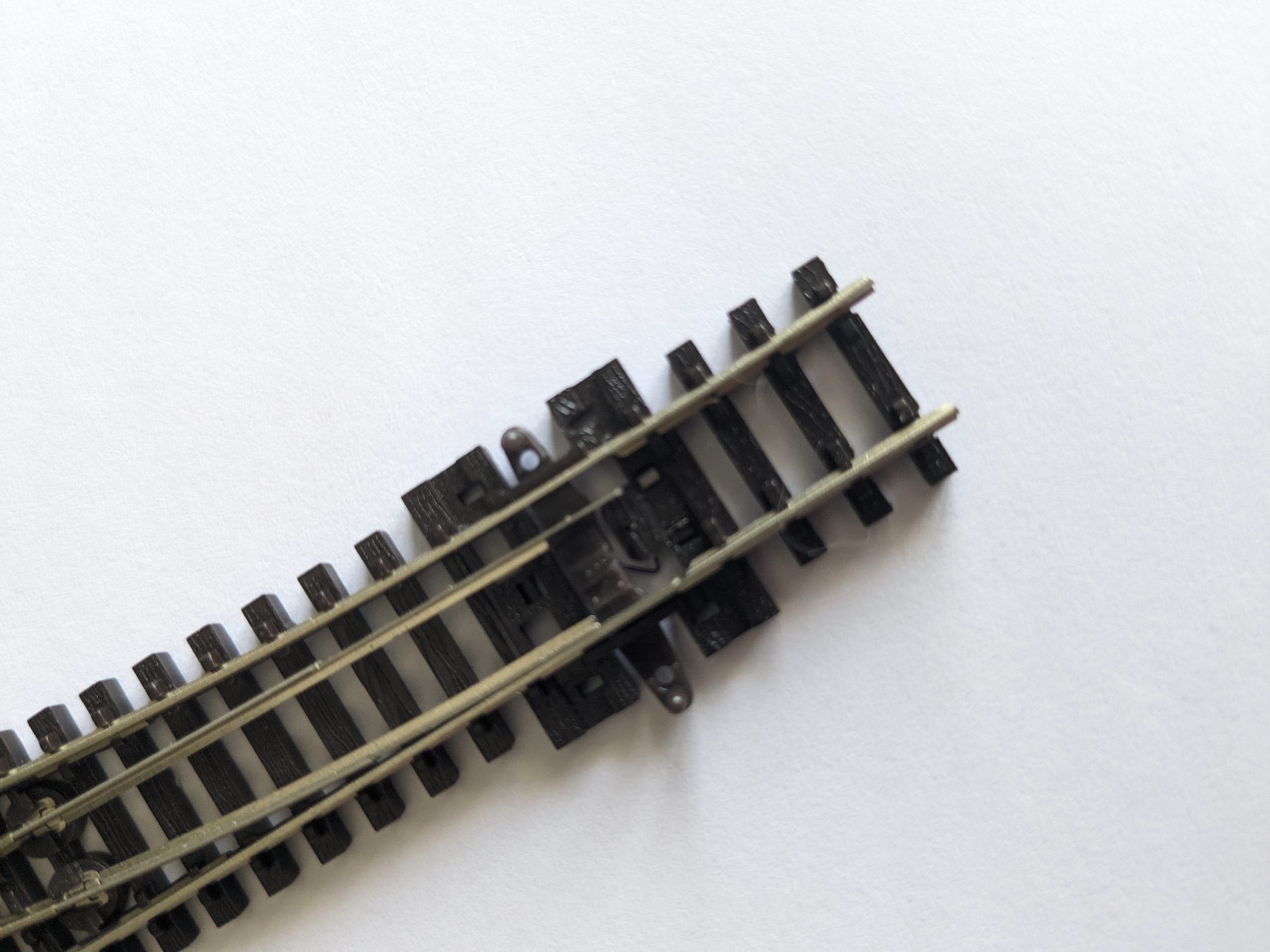
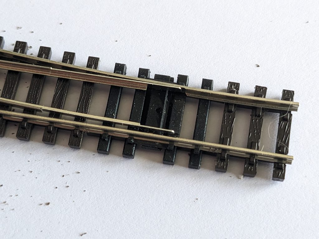
We’ve replaced the entire sleeper arrangement around the slider, replaced the slider and opened up the rail spacing so the movement of the point can be mush smaller. If you’re interested in these, we’ve added the product to our shop here for you to purchase and print at home.
Loco updates
Next up, we finally managed to get hold of a decoder for a Farrish 08 shunter we’ve had – a Zimo MN180 along with a STAC01 stay alive from YouChoos – that gives us 10 seconds of run time when the power is removed. Way overkill, but it works a treat!
Right that’s all for now. Tomorrow (October 1st) we’re off to the Dorking and Horsham exhibition so that will be in our October update.
Happy modelling!

