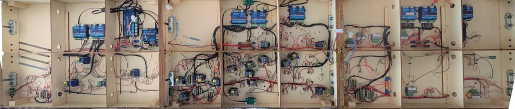
So as of mid-June we’re pretty much 95% wiring complete across all 3 boards that make up London Road, Derby and we’re now able to run trains across all the boards. In this post, we’re going to detail the underside of each of the boards and what is installed – here’s a look at what the underside looks like:
Board 1
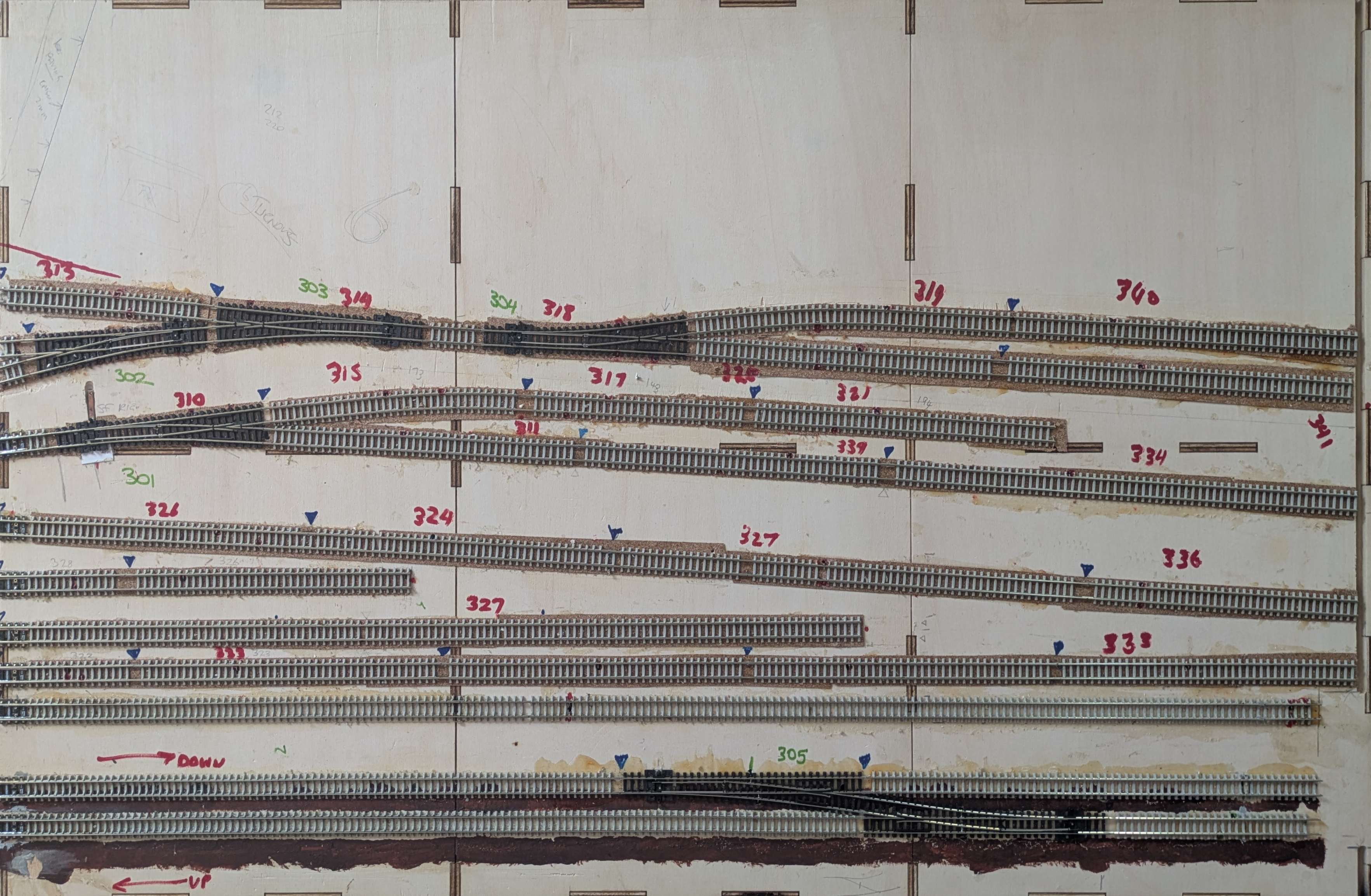
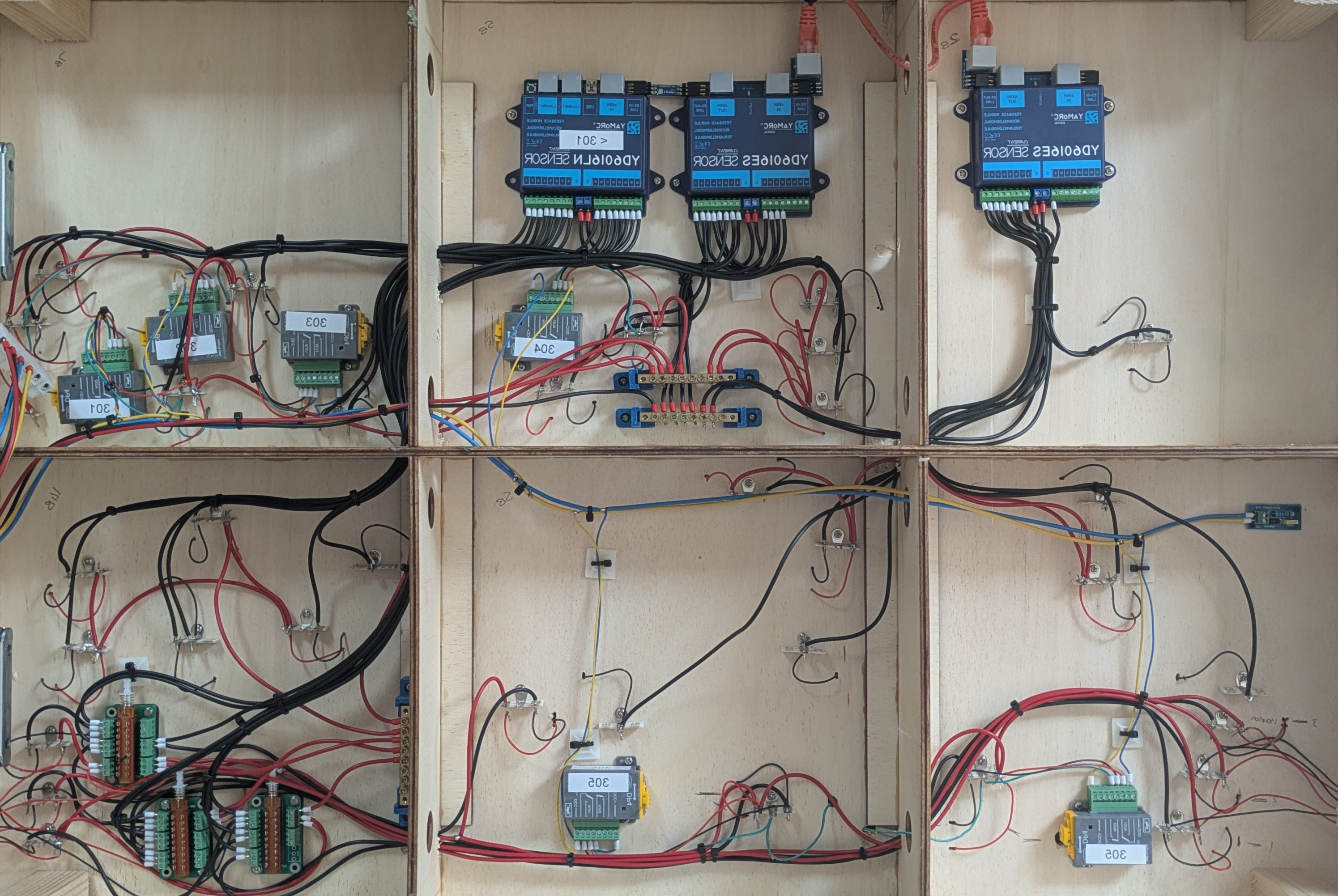
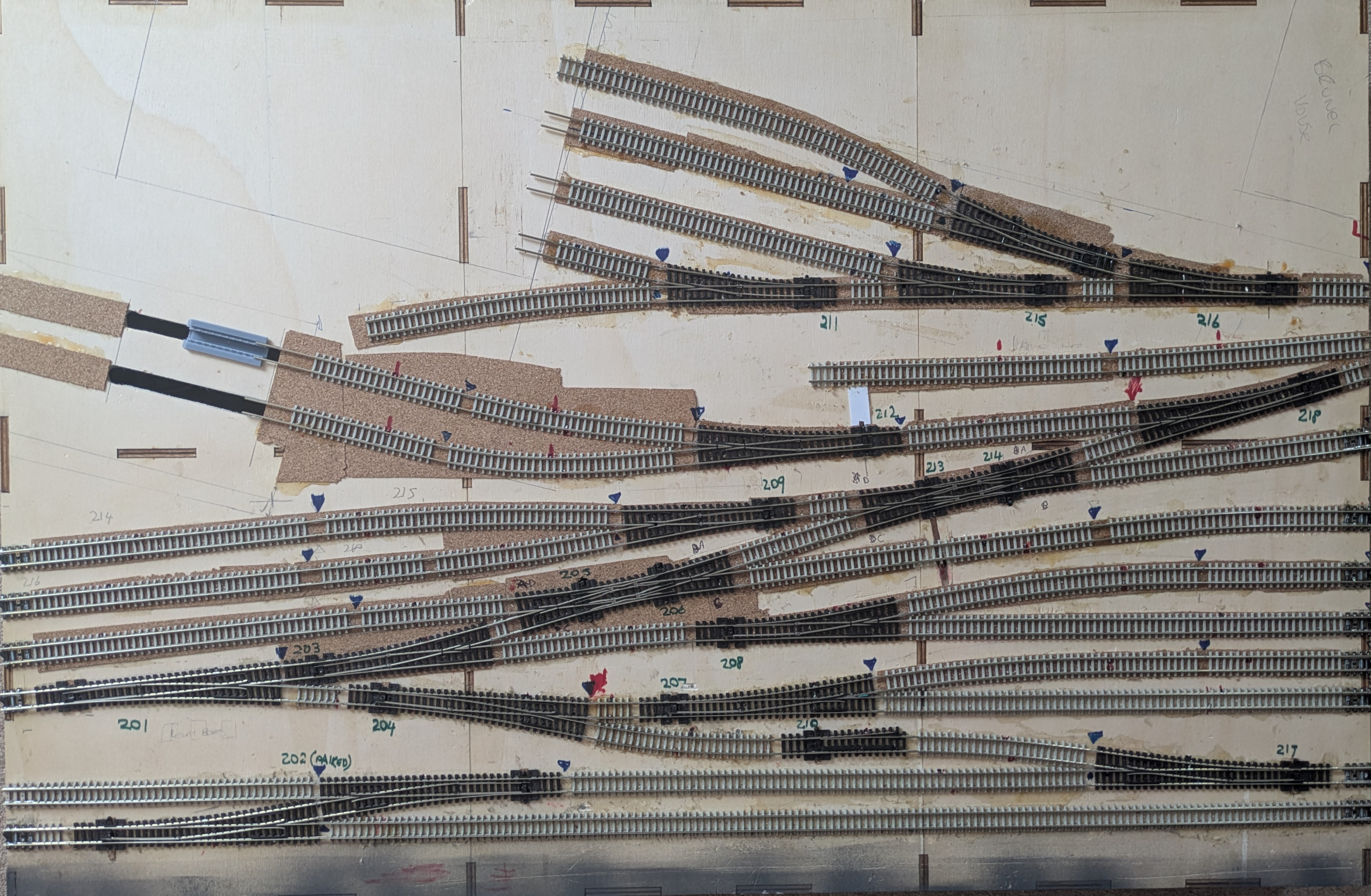
Starting on the left side, we have board 1 – this board is the simplest boards of the layout with only 4 turnouts and the first board we had operational some 16 months ago. This board houses the Yamorc YD7010 as well as the Yamorc YD7403 booster. Traction control is by the booster (red/black wires – red is common, black is used for detection via the YD6016s) and accessories are powered from the YD7010 (blue/yellow wires). Also on this board is a YD6016LN-CS connected to a YD6016ES-CS via YD6901ES-LINK module. Turnouts are operated by 4 DCC Concepts Cobalt Digital iP motors.
Down in the lower left corner of the board is a 6 way latch switch that is used to toggle Line 3 between the incoming connection or the ‘home’ DCC traction bus. Remember, the layout can also be used as part of a club modular layout so the power for Lines 1, 2 and 3 can be detached from the layout and use the incoming power connection specifically for those lines.
The 6 way latch switch allows the common red track connections to be toggled between the home DCC and the incoming connection as well as connecting all the isolated track sections to the detector in home mode and all of them together to whatever is being provided to the board via the board interconnect when in modular mode. This means that in modular mode using DC or DCC, trains can be brought into the layout, the latch switch toggled to reconnect line 3 to the home DCC and isolate from the incoming feed, the train marshalled and new one sent out and the retoggled and the new train departs.
A 4-way pluggable chocolate block takes the traction/accessory buses over to board 2 as well as a Loconet cable. This will be neatened up in the future so it’s just a single D-bus connector across the boards.
Here’s a closer look of board 1, drag the slider to compare the top and underside.
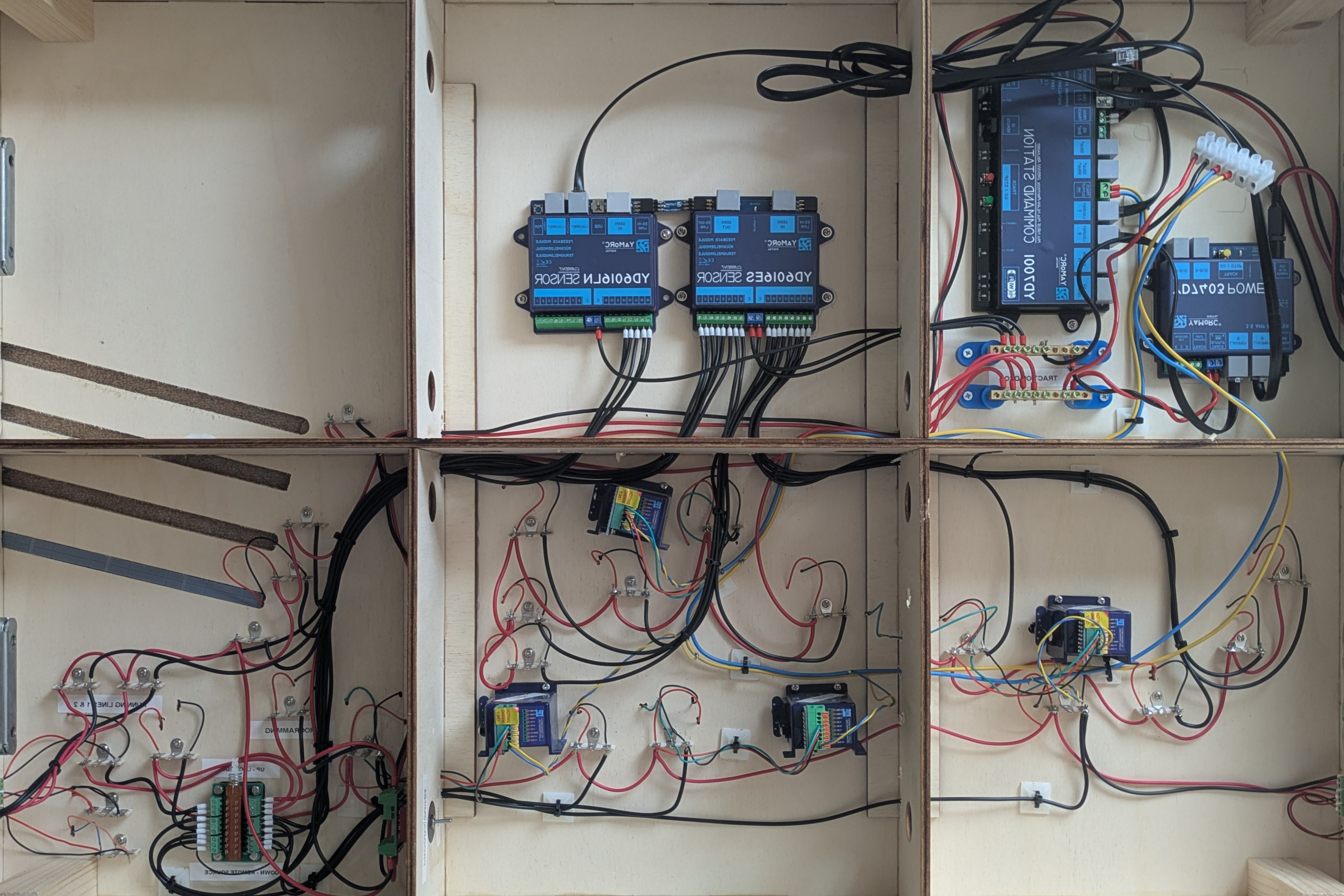
Board 2
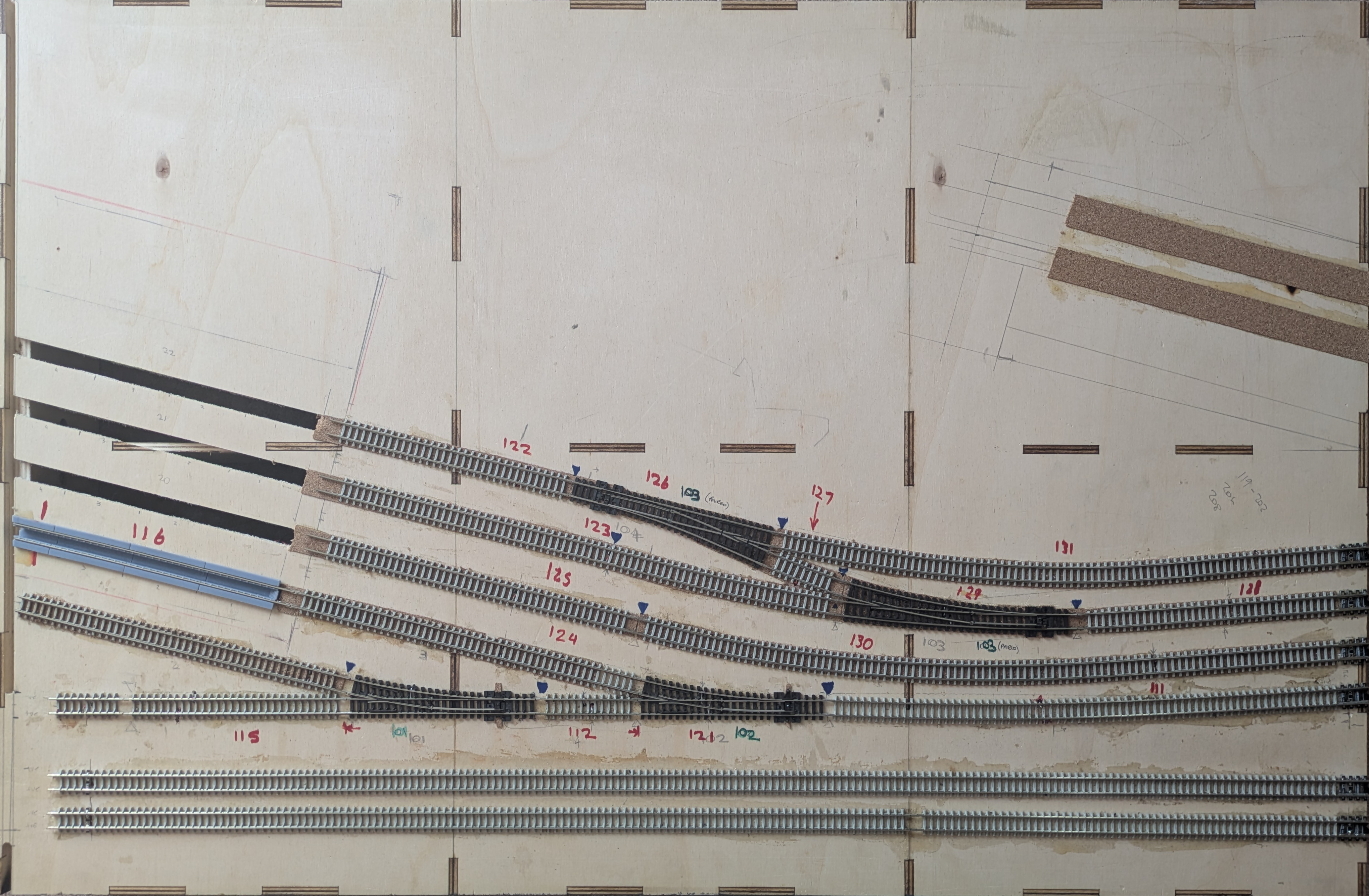
Moving onto board 2, the most complicated(?)/packed board of the layout, not helped by 15 DCC Concepts Cobalt Digital iPs with 4 left to install
A Yamorc YD6016LN-CS connected to a YD6016ES-CS via YD6901ES-LINK and then connected via YD6902ES-EXT (with RJ45 cable) to a second YD6016ES-CS
On the front and rear faces of the board are mounted 2 Digitrax UP7 universal panels to provide Loconet sockets for handsets etc – these are also connected to the raw (non-detected) DCC traction bus so the indicator light operates when track power is on.
Much like board 1, in the lower left corners are the 6 way latch switches to toggle lines 1, 2 and 3 from the home layout to the cross board connection for lines 1,2 & 3.
As with board 1, a 4-way pluggable chocolate block takes the traction/accessory over to board 3 as well as a Loconet cable.
Here’s a look at the top and underside of board 2.
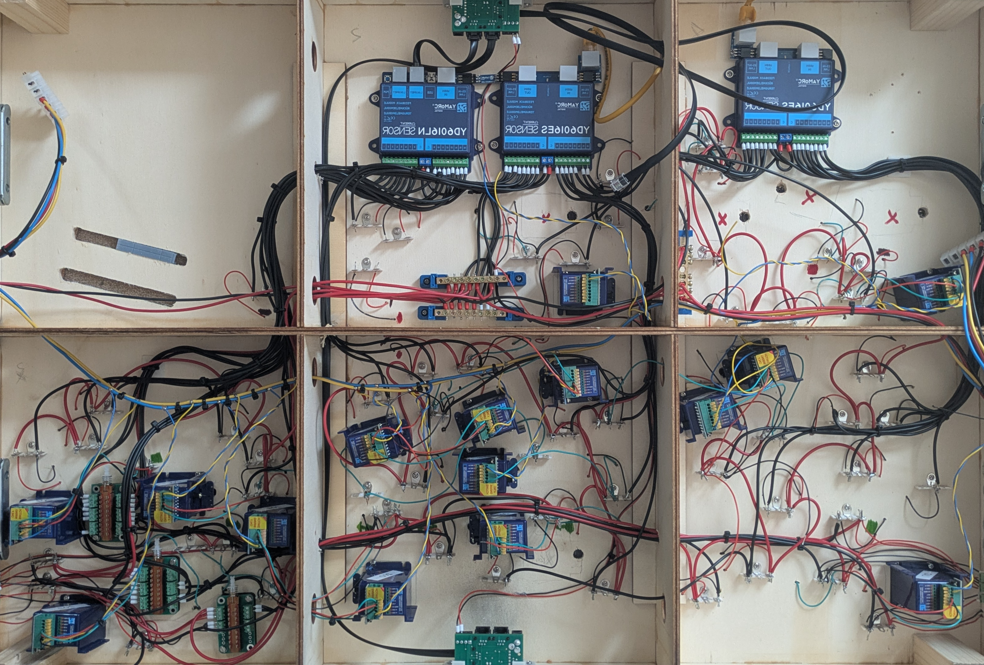
Board 3
Board 3 was the second board that was wired up. For this board, we tried something different and opted to use MTB DP4 Digital point motors and similar to board 2, a Yamorc YD6016LN-CS connected to a YD6016ES-CS via YD6901ES-LINK and then connected via YD6902ES-EXT (with RJ45 cable) to a second YD6016ES-CS is installed on the board.
The lower left corner then houses the 6 way latch switches for lines 1,2 & 3 for home vs modular mode.
Here’s what board 3 looks like underneath.